Screw Jacks

JTW Series Machine Screw Jacks
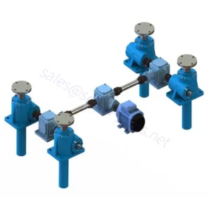
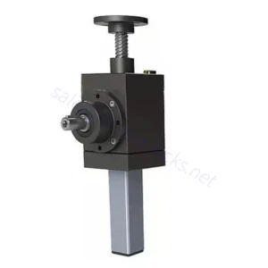
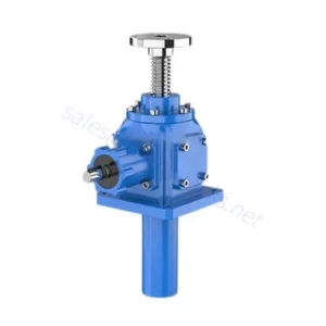
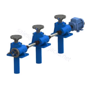
JTW Series Machine Screw Jack is a device used to apply a force, push and pull, lift and lower, open and close, or move to a position and hold by mechanically converting rotary motion into linear motion. Due to the classic design, you don’t need to attach any construction elements to the housing. In the absence of vibration load, they have self-locking, and precisely positioned loads will hold loads without back driving, and no need for any brake mechanism or locking system. It can be mounted in any attitude. Generally maintenance-free.
Mail:[email protected]
JTW Series Machine Screw Jack is a device used to apply a force, push and pull, lift and lower, open and close, or move to a position and hold by mechanically converting rotary motion into linear motion. Due to the classic design, you don’t need to attach any construction elements to the housing. In the absence of vibration load, they have self-locking, and precisely positioned loads will hold loads without back driving, and no need for any brake mechanism or locking system. It can be mounted in any attitude. Generally maintenance-free.
JTW-Series Machine Screw Jacks Key Features
* Self-locking machine screw, precise positioning, and uniform speed.
 |
 |
JTW-Series Machine Screw Jacks Specifications
| Model | JTW-1T | JTW-2.5T | JTW-5T | JTW-10T | JTW-15T | JTW-20T | JTW-25T | JTW-35T | JTW-50T | JTW-100T |
| Max. lifting force (ton) | 1 | 2.5 | 5 | 10 | 15 | 20 | 25 | 35 | 50 | 100 |
| Max. pulling force (ton) | 1 | 2.5 | 5 | 9.9 | 13.5 | 16.5 | 25 | 35 | 50 | 100 |
| Lifting screw sizes Tr (mm) | 24×4 | 30×6 | 40×7 | 58×12 | 58×12 | 65×12 | 90×16 | 100×20 | 120×20 | 160×23 |
| Gear ratio (H) | 1/6 | 1/6 | 1/6 | 1/8 | 1/8 | 1/8 | 3/32 | 3/32 | 3/32 | 1/12 |
| Lifting screw travel (mm) per turn of input shaft (H) | 0.67 | 1 | 1.167 | 1.5 | 1.5 | 1.5 | 1.5 | 1.875 | 1.875 | 1.92 |
| Efficiency % (H) | 21 | 23 | 21 | 20.5 | 20.5 | 19.5 | 16 | 18 | 15 | 13 |
| Gear ratio (L) | 1/24 | 1/24 | 1/24 | 1/24 | 1/24 | 1/24 | 1/32 | 1/32 | 1/32 | 1/36 |
| Lifting screw travel (mm) per turn of input shaft (L) | 0.17 | 0.25 | 0.29 | 0.5 | 0.5 | 0.5 | 0.5 | 0.625 | 0.625 | 0.639 |
| Efficiency % (L) | 13 | 11 | 11.5 | 13 | 13 | 12.8 | 9 | 11 | 11 | 10 |
| Idling torque (N.m) | 0.29 | 0.62 | 1.4 | 2 | 2.6 | 3.9 | 9.8 | 16.5 | 19.6 | 39.2 |
| Max. length of lifting screw (mm), when max. tensile force | 1200 | 1500 | 2000 | 2500 | 2500 | 3000 | 3500 | 4000 | 5500 | 6500 |
| Max. permissible power (kW) | 0.25 | 0.55 | 1.1 | 2.6 | 2.6 | 3.7 | 4.8 | 6 | 7.5 | 15 |
| Lubricant (kg) | 0.05 | 0.1 | 0.25 | 0.5 | 0.5 | 0.75 | 1.1 | 1.9 | 2.2 | 2.5 |
| Weight without stroke (kg) | 4 | 7.3 | 16.2 | 25 | 25 | 36 | 70.5 | 87 | 420 | 1010 |
| Weight of screw (kg) per 100 mm stroke | 0.3 | 0.45 | 0.82 | 1.67 | 1.67 | 2.15 | 4.15 | 5.2 | 7.45 | 13.6 |
|
Remarks:
1. H: high ratio, L: slow ratio
2. Max. Allowable power is under the conditions that ambient temperature is 20 degrees C, duty cycle 20%h, and input speed 1500rpm.
3. Efficiency is under grease lubrication.
4. Self-locking under static conditions, without vibration loads.
|
||||||||||
Trusted QC System
Quality is maintained throughout the ball screw lift manufacturing process, from material selection to mass production and packaging.
Our measuring room is equipped with modern three-dimensional measuring machines, which ensures that all of our products follow industry standards through various inspections and tests.
 |
 |
 |
| Housing Testing | Worm Shaft Testing | Housing Testing |
 |
 |
 |
| Worm Shaft Testing | Worm Wheel Testing | Ball Screw Testing |